Two batteries in parallel are easy: positive to positive, negative to negative, done. Four, six or eight are a different story. Wire them the "obvious" way, one after the other with the inverter on the first module, and the battery closest to the inverter quietly does most of the work. This guide compares the three ways to connect a lithium bank in parallel (daisy chain, cross-connected chain and busbar), explains when each one is good enough, and gives you a simple rule for choosing.
Up to three or four modules, a daisy chain with identical link cables is fine, as long as you cross-connect: inverter positive on the first module, inverter negative on the last. From about five modules, or whenever the inverter current is high, use a busbar pair with one equal-length cable from each module. Whatever the method, all cables to the same point must be the same length and section.
The problem: unequal current sharing
Batteries in parallel share a common voltage, but they do not automatically share the current equally. Each module delivers current in proportion to how easy its path to the load is, that is, inversely to the resistance of that path. Cable, connectors and every contact in between add up.
In a simple chain where the inverter connects to battery 1, the current from battery 4 must travel through three sets of link cables to get out, while battery 1 has none. The difference per link is small, a few milliohms, but it is systematic. Battery 1 ends up charging and discharging a little harder on every single cycle, runs slightly warmer, and over years ages a little faster than the others.
Modern lithium batteries with a BMS and communication between modules (like Pylontech's master/slave setup) cope with this better than lead-acid did, and the BMS keeps each module within safe limits. But "within safe limits" is not the same as "evenly used". Good wiring is still the cheapest way to make a bank last.
Option 1: simple daisy chain
Every module is connected to the next with a pair of link cables, and the inverter's positive and negative cables both connect to the first module.
- Pros: fewest cables, tidy, and it is the layout most battery kits are designed for.
- Cons: worst current sharing. The first module carries the whole bank's current through its terminals, and the far modules are under-used.
- When it is acceptable: two modules, or three with low inverter current.
Option 2: cross-connected chain (the free upgrade)
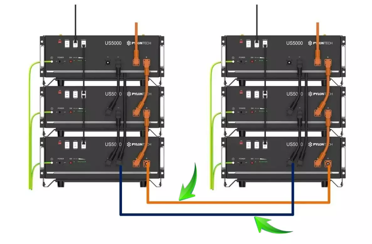
Same link cables, one change: the inverter positive goes to the first module and the inverter negative to the last module. Now every module has the same total path length (some on the positive side, some on the negative side), and current sharing improves a lot without buying anything.
- Pros: costs nothing more if your main cables reach, and the sharing is much more even.
- Cons: needs a longer negative main cable to reach the last module. The link cables near the ends still carry more current than those in the middle.
- When it is ideal: three to four modules, typical home inverters.
The communication chain is independent from the power wiring. Whatever you do on the power side, the master battery (the one that talks to the inverter over CAN or RS485) stays at the start of the RJ45 chain: its LINK PORT 1 goes to LINK PORT 0 of the next module, and so on. Cross-connecting the power cables does not change which module is master.
Option 3: busbar pair
Each module gets its own pair of cables to a positive busbar and a negative busbar. The inverter connects to the busbars, ideally in their centre. Each module now has an identical path to the inverter, provided all module cables are the same length.
- Pros: the best current sharing; no module's terminals carry another module's current; easy to isolate one module for service (especially with a fuse or breaker per string).
- Cons: more cables and connectors, the busbars themselves (correctly rated, insulated and covered), and more space.
- When it is the right choice: five modules or more, high-power inverters, or several racks.
Side-by-side comparison
| Daisy chain | Cross-connected chain | Busbar | |
|---|---|---|---|
| Current sharing | Uneven | Good | Best |
| Extra material | None | Longer negative main cable | Busbars + one cable pair per module |
| Current through the first module's terminals | Whole bank | Half the path on each side | Only its own |
| Service one module | Breaks the chain | Breaks the chain | Disconnect only that module |
| Recommended size | 2 modules | 3 to 4 modules | 5 modules and more |
Choosing the cables for each method
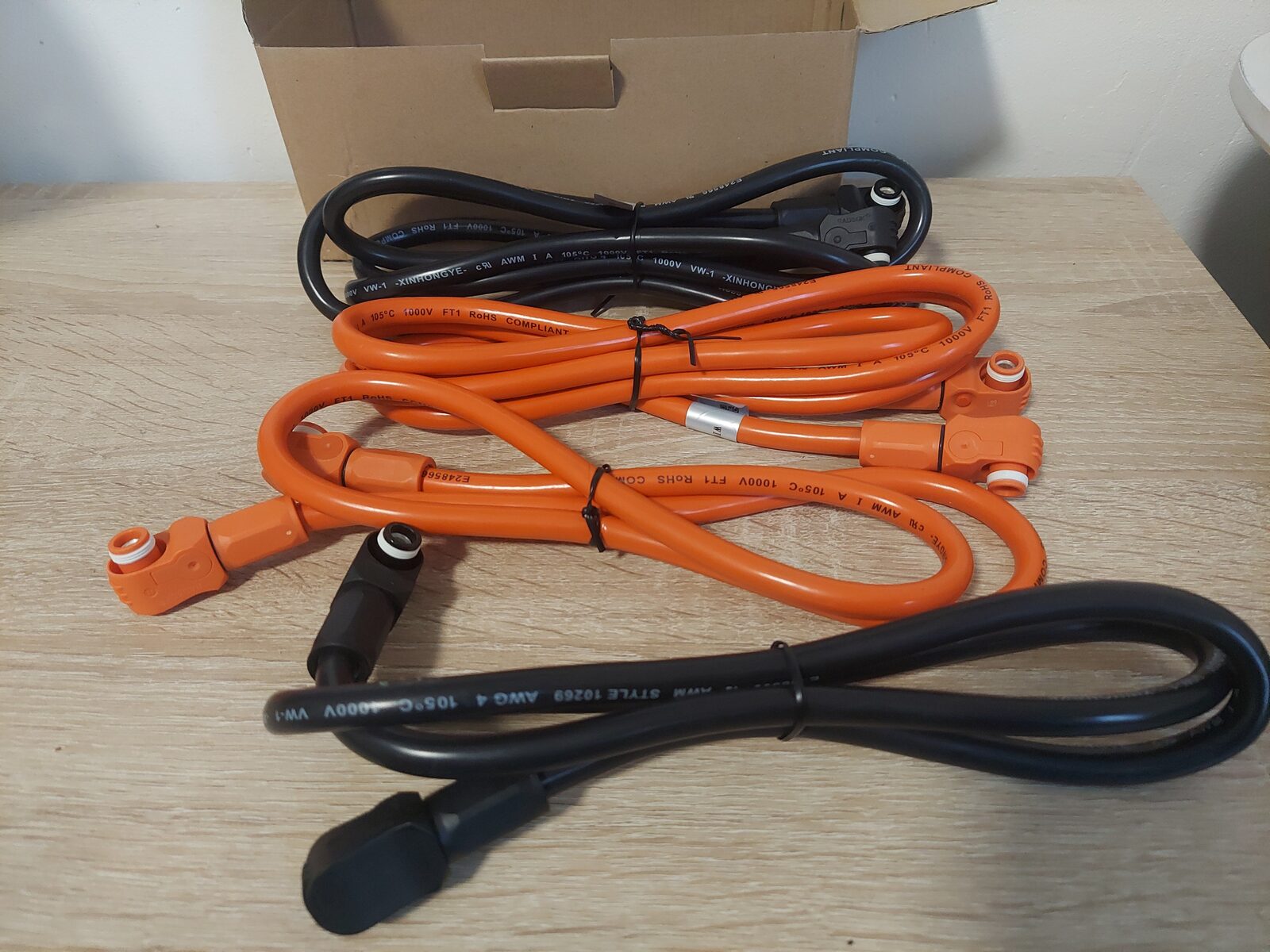
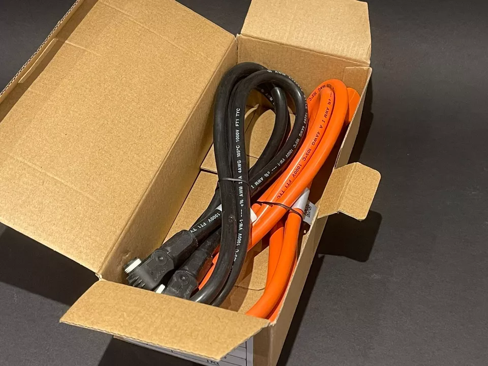
For chains, use pairs of identical link cables with the battery's own connector at each end. On Pylontech, BYD, Goodwe, Dyness and similar modules that means Amphenol SURLOK Plus plugs, in the length your rack spacing requires: 48 cm, 70 cm, 1 m or 2 m. For the long negative of a cross-connected chain, the main cable must have the same section as the positive.
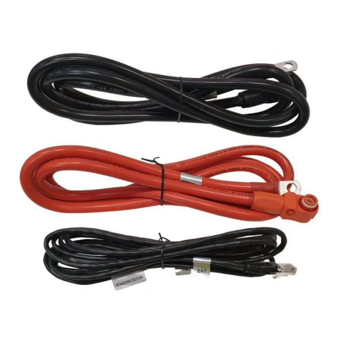
For busbars, each module needs a cable with the battery connector on one end and a ring lug sized for the busbar stud on the other. Our Amphenol/M8 kit covers the common Pylontech-to-M8 case, and the custom configurator handles other lugs and lengths. Remember the rule: every module-to-busbar cable the same length, even if some modules sit closer.
Not sure about the section? Our guide on cable gauge for lithium batteries in parallel explains how to size it.
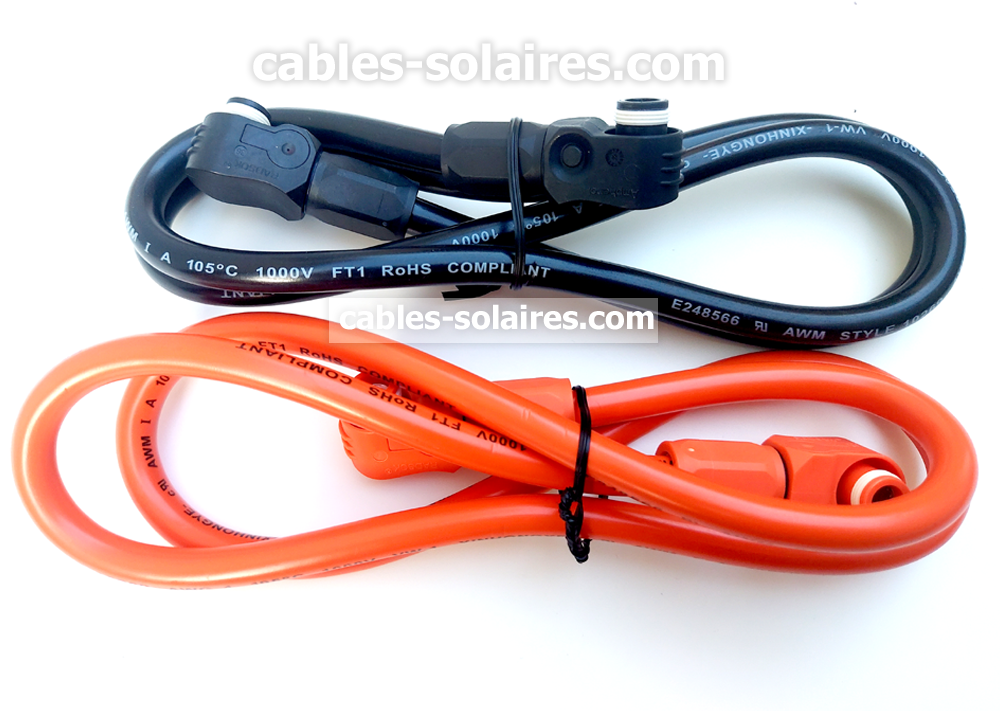
Matched cables for any topology
Amphenol-to-Amphenol links for chains, Amphenol-to-M8 cables for busbars, all in 25 mm² tinned copper and built to identical lengths.
Fuses, breakers and busbar safety
A busbar concentrates the energy of the whole bank in two bars of copper. Treat it accordingly:
- Use busbars rated above the maximum current of the bank, with insulating covers.
- Protect the main cable to the inverter with a fuse or breaker sized for that cable, as close to the busbar as practical.
- On larger banks, a fuse or breaker per module lets you isolate one module safely and protects each cable individually.
- Tighten studs to the busbar manufacturer's torque, and re-check after the first weeks: copper settles.
Each lithium module's own BMS and power switch protect the module itself. They are not a substitute for protecting the main cables between the bank and the inverter.
How to check that your bank shares the load
The simplest test is temperature: after a long, heavy discharge, all module terminals should feel the same, and no cable or connector should be noticeably warm. A clamp meter on each module's positive cable during a steady discharge gives you numbers: on a well-wired bank they should be close to each other.
On Pylontech systems, a battery monitor that reads every module, such as the Pylon-Monitor, shows current, temperature and state of charge per module over time. A module that is always a few percent ahead or behind, or always warmer, is often a wiring clue.
Frequently asked questions
How many batteries can I connect in a daisy chain?
Technically the battery manufacturer sets the limit (Pylontech allows up to 16 modules per group). For current sharing, a simple chain is best kept to two or three modules; with cross-connection, four is fine. Beyond that, a busbar gives better results.
Is cross-connecting safe?
Yes. It is standard practice for parallel battery banks: positive from the first module, negative from the last. Polarity at each module is unchanged; only the point where the inverter connects moves.
Do I still need communication cables with a busbar?
Yes. On Pylontech systems, the RJ45 link chain between modules and the master-to-inverter cable are independent from the power wiring and are required whatever topology you use.
Do all busbar cables really need the same length?
Yes. The whole point of the busbar is that each module has the same path to the inverter. A shorter cable on one module gives it a lower resistance and more current, which recreates the problem the busbar was meant to solve.